I decided I wanted to be able to control my garage door using my phone. After some research, I decided to use an ESP8266 based Wemos D1 Mini and Home Assistant.
Here are the parts that will be needed:
- Wemos D1 Mini | AliExpress
- MicroUSB Cable and Charger for Wemos
- 5V Relay | AliExpress
- Magnetic Reed Switch/Door Sensor | AliExpress
- 22 Gauge 2 Conductor Wire
- Electronic Project Case (Optional)
Software Requirements:
- Home Assistant configured with an MQTT broker such as Mosquitto
- Arduino IDE
I’m going to assume that Home Assistant, MQTT, and Arduino IDE are all setup. There are plenty of guides out there on how to set those up. If anyone reading this does need help with any of that, feel free to post a comment.
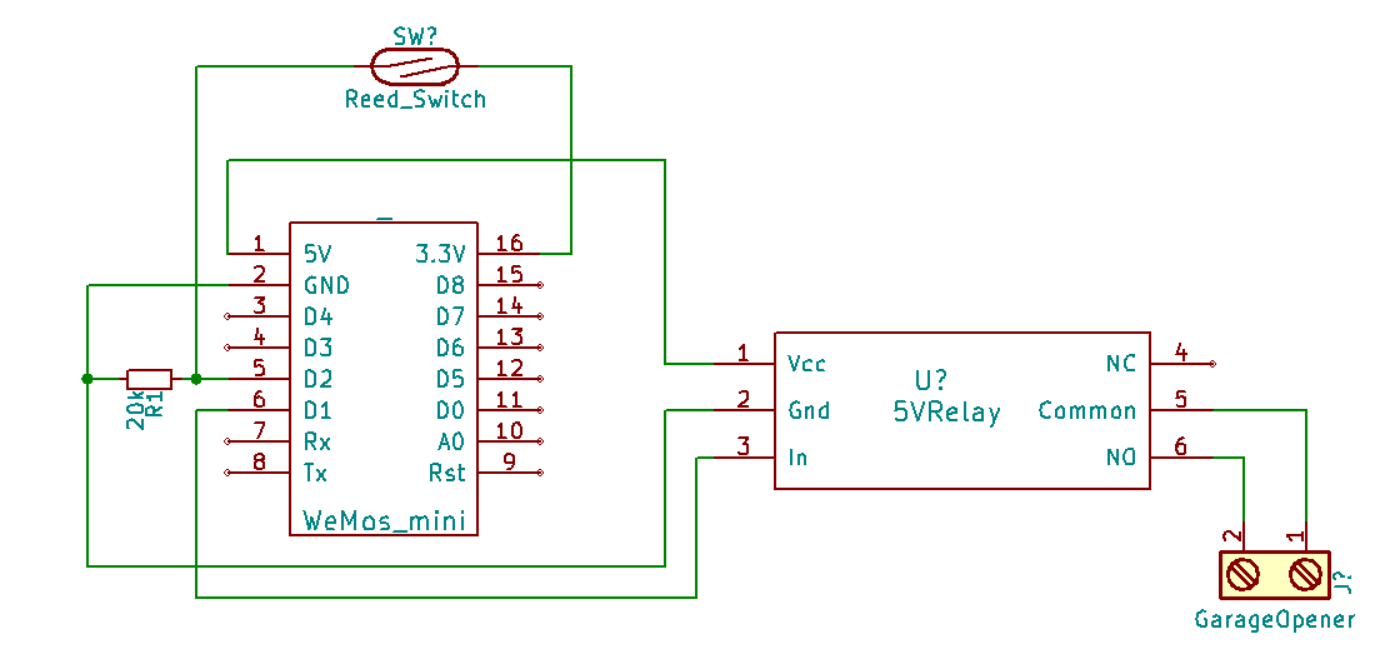
- The first thing we will need to do is wire up the Wemos. The schematic below shows how I wired mine. If for any reason, you don’t use the same pins as I did on the Wemos, keep in mind that the chip will send some pins to high on startup. That would trigger the relay, and unexpectedly open your garage door. Be mindful of which pin you use.

Garage Door Opener Wemos Schematic 
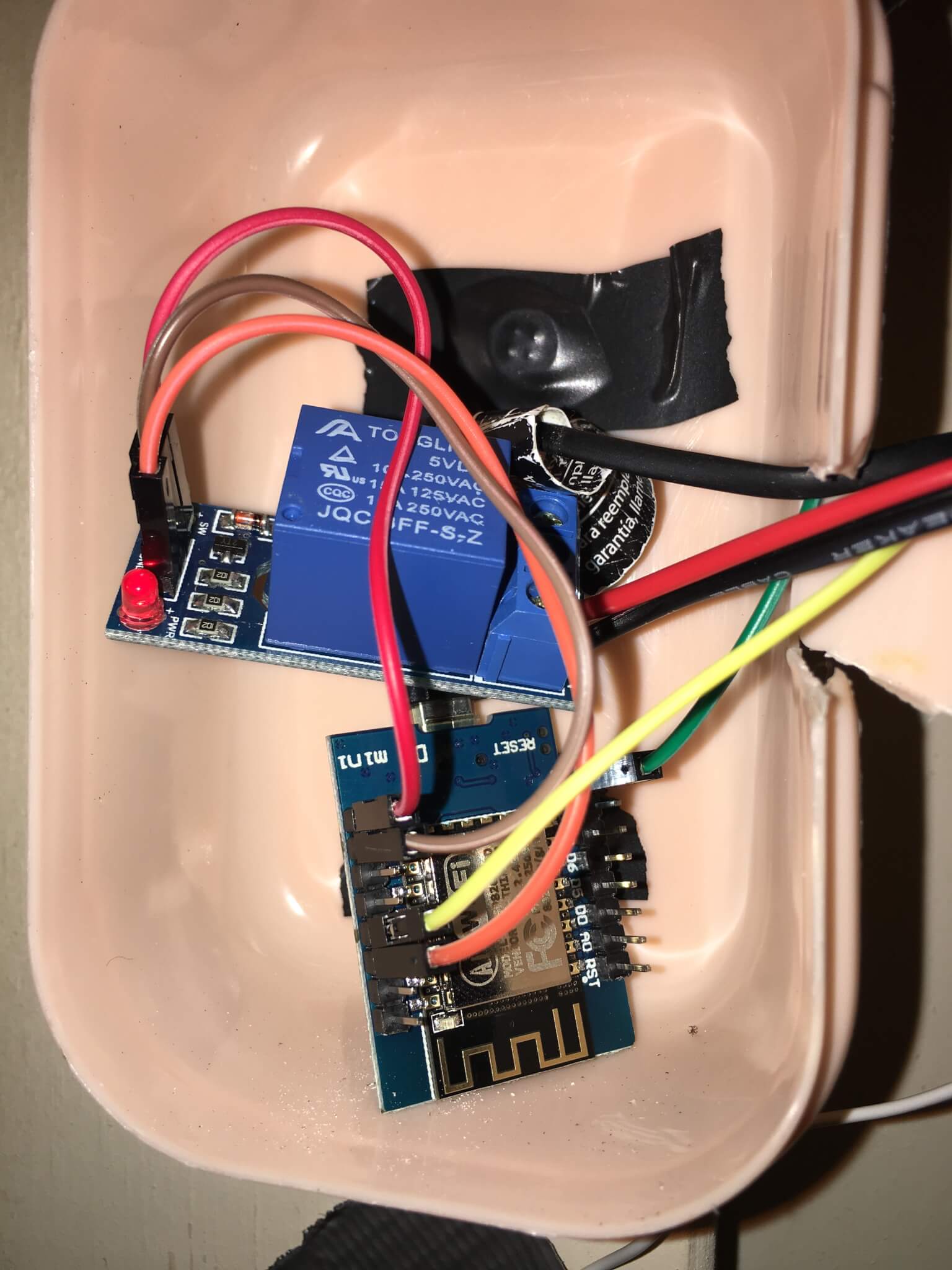
My Wemos and relay. - Next, we need to upload the code below to the Wemos. You will need to edit the custom parameters section as needed. The first time you upload the firmware, you will need to do it via serial using a USB cable. After the firmware is on there, you can do the updates Over-The-Air (OTA). The code below uses WifiManager, which starts the Wemos as an AP if it can’t connect to a Wifi network. You can then connect to the AP to setup Wifi on the Wemos. The settings will be saved across reboots.
For OTA, in Arduino IDE, click Tools -> Flash Size -> 4M (1M SPIFFS). If you don’t do this, the firmware will not work on the Wemos. Next, compile it in Arduino IDE using CTRL+ALT+S. That will compile a *.bin file in the same directory as your *.ino. You can use your web browser to go to http://<Wemos IP>/WebFirmwareUpgrade and upload the *.bin file. It will then reboot in about 30 seconds with the new code.
- The first thing we will need to do is wire up the Wemos. The schematic below shows how I wired mine. If for any reason, you don’t use the same pins as I did on the Wemos, keep in mind that the chip will send some pins to high on startup. That would trigger the relay, and unexpectedly open your garage door. Be mindful of which pin you use.
#include <ESP8266WiFi.h>          //ESP8266 Core WiFi Library (you most likely already have this in your sketch)
#include <DNSServer.h>            //Local DNS Server used for redirecting all requests to the configuration portal
#include <ESP8266WebServer.h>     //Local WebServer used to serve the configuration portal
#include <WiFiManager.h>          //https://github.com/tzapu/WiFiManager WiFi Configuration Magic
#include <PubSubClient.h>         //MQTT
#include <ESP8266mDNS.h>
#include <ESP8266HTTPUpdateServer.h>

////**********START CUSTOM PARAMS******************//

//Define parameters for the http firmware update
const char* host = "GarageESP";
const char* update_path = "/WebFirmwareUpgrade";
const char* update_username = "admin";
const char* update_password = "YourPassWordHere";

//Define the pins
#define RELAY_PIN 5
#define DOOR_PIN 4

//Define MQTT Params. If you don't need to
#define mqtt_server "MQTT Broker IP Address"
#define door_topic "garage/door"
#define button_topic "garage/button"
const char* mqtt_user = "mqtt_user";
const char* mqtt_pass = "mqtt_pass";

//************END CUSTOM PARAMS********************//
//This can be used to output the date the code was compiled
const char compile_date[] = __DATE__ " " __TIME__;

//Setup the web server for http OTA updates.
ESP8266WebServer httpServer(80);
ESP8266HTTPUpdateServer httpUpdater;

WiFiClient espClient;

//Initialize MQTT
PubSubClient client(espClient);

//Setup Variables
String switch1;
String strTopic;
String strPayload;
char* door_state = "UNDEFINED";
char* last_state = "";

//Wifi Manager will try to connect to the saved AP. If that fails, it will start up as an AP
//which you can connect to and setup the wifi
WiFiManager wifiManager;
long lastMsg = 0;

void setup() {
  //Set Relay(output) and Door(input) pins
  pinMode(RELAY_PIN, OUTPUT);
  pinMode(RELAY_PIN, LOW);
  pinMode(DOOR_PIN, INPUT);

  Serial.begin(115200);

  //Set the wifi config portal to only show for 3 minutes, then continue.
  wifiManager.setConfigPortalTimeout(180);
  wifiManager.autoConnect(host);

  //sets up the mqtt server, and sets callback() as the function that gets called
  //when a subscribed topic has data
  client.setServer(mqtt_server, 1883);
  client.setCallback(callback); //callback is the function that gets called for a topic sub

  //setup http firmware update page.
  MDNS.begin(host);
  httpUpdater.setup(&httpServer, update_path, update_username, update_password);
  httpServer.begin();
  MDNS.addService("http", "tcp", 80);
  Serial.printf("HTTPUpdateServer ready! Open http://%s.local%s in your browser and login with username '%s' and your password\n", host, update_path, update_username);
}

void loop() {
  //If MQTT client can't connect to broker, then reconnect
  if (!client.connected()) {
    reconnect();
  }
  checkDoorState();
  client.loop(); //the mqtt function that processes MQTT messages
  httpServer.handleClient(); //handles requests for the firmware update page
}

void callback(char* topic, byte* payload, unsigned int length) {
  //if the 'garage/button' topic has a payload "OPEN", then 'click' the relay
  payload[length] = '\0';
  strTopic = String((char*)topic);
  if (strTopic == button_topic)
  {
    switch1 = String((char*)payload);
    if (switch1 == "OPEN")
    {
      //'click' the relay
      Serial.println("ON");
      pinMode(RELAY_PIN, HIGH);
      delay(600);
      pinMode(RELAY_PIN, LOW);
    }
  }
}

void checkDoorState() {
  //Checks if the door state has changed, and MQTT pub the change
  last_state = door_state; //get previous state of door
  if (digitalRead(DOOR_PIN) == 0) // get new state of door
    door_state = "OPENED";
  else if (digitalRead(DOOR_PIN) == 1)
    door_state = "CLOSED";

  if (last_state != door_state) { // if the state has changed then publish the change
    client.publish(door_topic, door_state);
    Serial.println(door_state);
  }
  //pub every minute, regardless of a change.
  long now = millis();
  if (now - lastMsg > 60000) {
    lastMsg = now;
    client.publish(door_topic, door_state);
  }
}

void reconnect() {
  //Reconnect to Wifi and to MQTT. If Wifi is already connected, then autoconnect doesn't do anything.
  wifiManager.autoConnect(host);
  Serial.print("Attempting MQTT connection...");
  if (client.connect(host, mqtt_user, mqtt_pass)) {
    Serial.println("connected");
    client.subscribe("garage/#");
  } else {
    Serial.print("failed, rc=");
    Serial.print(client.state());
    Serial.println(" try again in 5 seconds");
    // Wait 5 seconds before retrying
    delay(5000);
  }
}
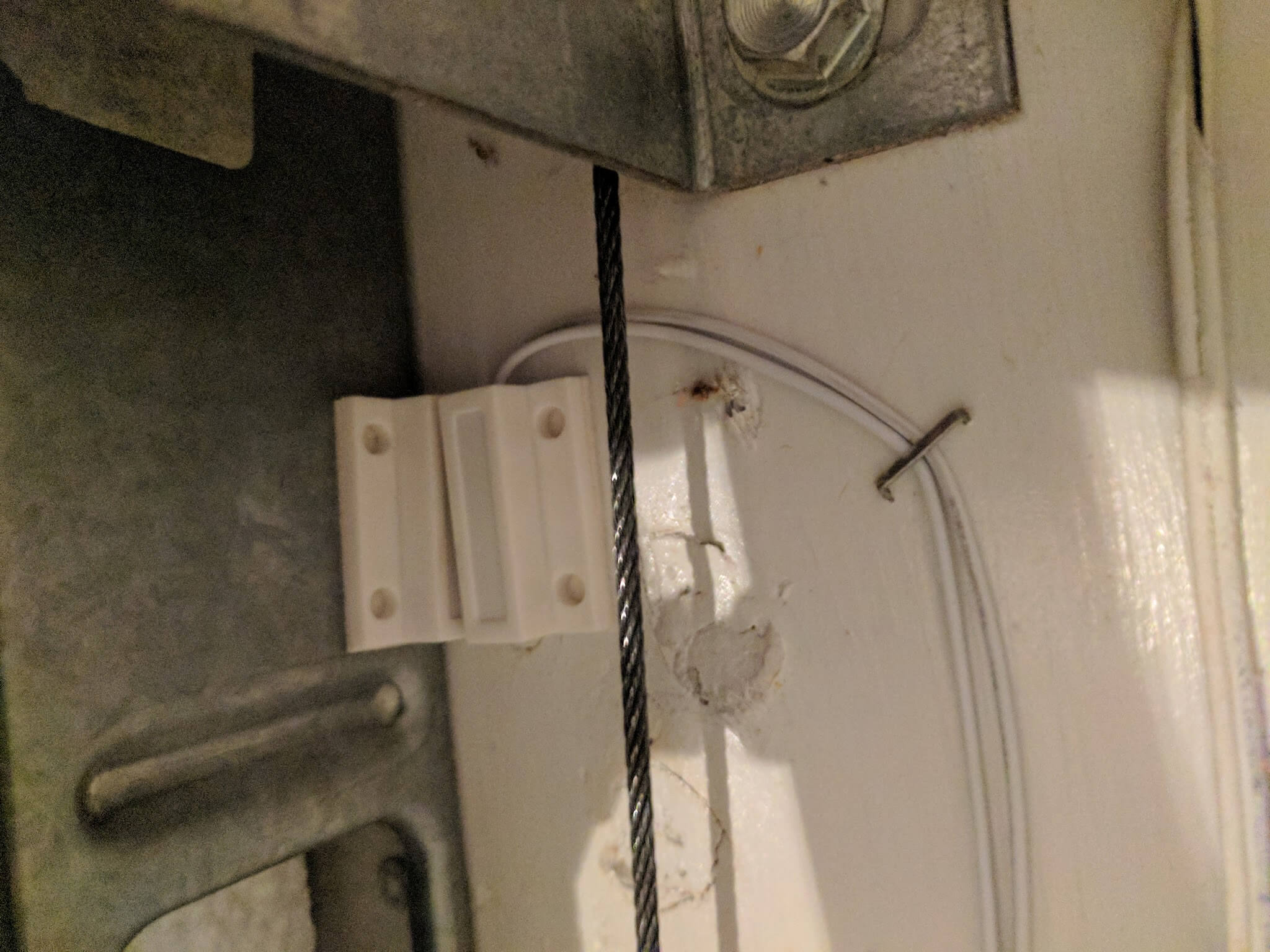
- Now to connect it to the garage door opener. The wired piece of the reed switch will go onto the wall, right next to the garage door. The other part of the reed switch will go on the door itself. You want to be very careful here to make sure that piece is in a place where it won’t get knocked off by something when the garage door moves up.

The reed switch (The wired piece) has to be within about 1/4″ from the magnetic piece when the door is closed. Note the red wire in the first terminal, and the black wire on the second terminal. These are going into Common and NC on the relay. On the garage door opener itself, you need to find the terminals where the wires for the wall button are located. You will most likely have 4 or more terminals. Two of those terminals are for the wall button. If you can’t figure out which ones they are, then you can try just taking a wire and shorting 2 terminals at a time until the door opens. Or you can disconnect one wire at a time until the button stops working.Once you have found those 2 terminals, connect a wire to each one. The other end of one of the wires(it doesn’t matter which one) goes to the Common terminal on the relay. The other wire connects to the NO (normally open) terminal. Now you can put it in the case and power it up.
- The last thing that is left to do is configure Home Assistant. To do that, simply add in the following code into your *.yaml file. This configuration sends the appropriate payload via MQTT to open/close the door, and looks for the payload based on the sensor to determine if the door is closed or not:
cover:
  - platform: mqtt
    name: Garage Door
    friendly_name: Garage
    state_topic: "garage/door"
    command_topic: "garage/button"
    payload_open: "OPEN"
    payload_close: "OPEN"
    payload_stop: "OPEN"
    state_open: "OPENED"
    state_closed: "CLOSED"
    optimistic: false
    retain: false
    value_template: '{{ value }}'
The garage door should show up in Home Assistant as a Cover. You can tell the state of the door based on which arrow is grayed out.

I Have a question about the wirinf schematic. Is it neccrsary to use a resistor?
The purpose of that resistor is to ‘pull down’ pin D2 to ground by default. This helps prevent things like interference from making D2 appear to be high when it is not. It’s not absolutely required, but you might get some false positives where the ESP thinks the door is open when it is actually not.
I don’t really recommend not using a resistor in your final project, but you should be fine for testing. Resistors don’t cost very much, so it’s better to be safe.
Let me know if you need any more help with it.
Oke Thank you, what type of resistor should i use?
I used a 20,000 Ohm resistor. Here’s a link to buy a variety pack of resistors. http://amzn.to/2mibnYc
And a link to buy from AliExpress if you aren’t in the US:
http://s.click.aliexpress.com/e/rjiqvF2
Thank you
I dont see a resistor in the picture and i am a noob to this electrical stuff. would you mind showing me how you wired this resistor for learning purposes?
The resistor is there in the schematic. You can basically just connect it directly from D2 to Ground. Let me know if you still need help with it.
The Esp8266 has an internal pullup. Just use this to set the pin mode:
pinMode(DOOR_PIN, INPUT_PULLUP);
Then check the state of the door by switching 1 and 0 in the original code
if (digitalRead(DOOR_PIN) == 1) // get new state of door
door_state = “OPENED”;
else if (digitalRead(DOOR_PIN) == 0)
door_state = “CLOSED”;
Then hook the reed switch up to DOOR_PIN on one end and GND on the other.
Put my version of the code up if you want to see https://github.com/johnboiles/esp-garage-opener
Hi friends can someone help me triger the relay with a mqtt pub command i have tried it all. The device is working i can see the sensor in mqtt.fx it responds nicely opened/closed. But the relay is something i canot figure it out.
I publish to it:
garage_door/switch:OPEN
i changed the topic in the code to my own.
Thanks for this John. I had read a little about this a while ago. I just did some more reading on it and it makes sense to me now. But, from what I’m seeing, the Pull-Up is only on pins 0 and 2, right? And I think 2 can’t be used on the wemos because it’s the built-in LED. And it looks like pin 15 has a pull down. Or am I wrong about this? Here’s the URL of what I read: http://escapequotes.net/esp8266-wemos-d1-mini-pins-and-diagram/
Oh interesting, yeah I should look closer. I’m using a NodeMCU v1.0 because it’s what I had on hand.
Trying to track down the source of truth on this. Seems like all the docs I’m finding from Espressif that mention the pull-ups say there are configurable pullups on every pin on the ESP8266 except for GPIO16 (D0 on the Wemos D1 Mini).
http://bbs.espressif.com/download/file.php?id=893&mode=view
https://cdn-shop.adafruit.com/product-files/2471/0A-ESP8266__Datasheet__EN_v4.3.pdf
Super weird though that the official Wemos D1 Mini documentation (https://wiki.wemos.cc/products:d1:d1_mini) only mentions pull-ups on those specific pins. But since the Espressif docs say otherwise, I think the D1 Mini docs are incorrect.
Let me know if you find info otherwise.
That is pretty much what I am seeing. I would think the expressif is more accurate.
If I had to guess, the expressif is more accurate in that the pull up/down is configurable. Maybe on the Wemos, it’s set and you can’t change it. I don’t see how a dev board can add a resistor and make it change via code.
Simit, Noob here. is it possible to put up a quick picture of how the resistor is connected? i am still learning and would like to know how this all works. Great project!
where can I download code thanks
I cant figure out how to get code when I hit ctl alt s my computer brings up a hp screen please any help would be great
You just need to select the code and copy it and then paste it into Arduino IDE.
ok thank you where do I past I mean this my screen
void setup() {
// put your setup code here, to run once:
} do I put it here
void loop() {
// put your main code here, to run repeatedly:
or here or booth
sorry to bug you but this project is awesome thanks
You’re not bugging me. Sorry for taking so long to respond. But you can just delete that code that is there and paste my code in.
Great project – I have a very similar setup. FYI, another option for the open/closed sensor is something like this: http://www.smarthome.com/seco-larm-sm-226l-3-magnetic-garage-door-contact-switch.html
I have one of those for each of my garage doors.
Thanks. I think the thing you linked to is effectively the same thing but with a little stronger magnet.
Awesome project. I did something very similar just using a basic HTTP server on the ESP8266 and Tasker + AutoRemote on my Android phone to receive notifications of the door changing status and also send a command to open / close. Haven’t explored Home Assistant yet, but I’ll have to check it out sometime!
How does the front-end work? Is it a website hosted by Home Assistant that you can access on any device or is it an app that you have to configure?
Thanks!
Thanks. Your best bet is to just check out the home assistant website. HA can run on a Linux or Windows box or even just a raspberry pi. You install it and configure it like I have shown to add sensors. You could probably even add your garage door without Any modification of the ESP.
Home assistant has a nice quick Web interface. Of you make it public facing you can access it from anywhere but I wouldn’t recommend that because of the security risks.
Let me know if you have any more questions.
Thanks for a great article. I am just getting started in ESP8266 and home automation and I really enjoyed your blog.
However ( at least it is not a but…) I would recommend adding a flyback diode (usually use 1N4407 ) across the VCC and GND pins of the relay.
See this link for an interesting experiment as to why one is required. https://electronics.stackexchange.com/questions/146499/relays-flyback-diode-is-it-necessary/146514
Thanks for the feedback. I’m a beginner with all this. I’ll check that out.
I just checked that out and I’m not sure if I need that. It looks like it might only be the case if a transistor is used. What do you think?
Did you ever get a chance to update this an include a DHT for temp and humidity? Great project!
I never had any plans to add one. I think someone on one of the posts on the Home Assistant forum might have mentioned they wanted to do that. I’m not sure they ever did that.
Instead of using a Reed Switch is it possible to use a magnetic door sensor?
Rooney, I could be wrong, but I think that they are the same thing, so yes.
What type of wire should I be buying to lead into the opener? Is there a particular gauge you recommend? I am looking to buy long lengths of it because my power outlet is a ways away from the opener. Thanks for any help!
Sarah, THIS should work for you. Those are each 33 feet long. I’m using about a 25 run myself. Considering the fact that it’s not really pushing a whole lot of current, pretty much any wire should work. Let me know if you need any more help with it.
Simit – thanks very much for posting this project, it’s exactly what I’m after. For the hookup wire, old telephone cords work well for this sort of thing. Just cut the ends off.
You can also use standard garage door opener wire.
parts of code i had to modify for it to work for me. otherwise relay would not work
void setup() {
//Set Relay(output) and Door(input) pins
pinMode(RELAY_PIN, OUTPUT);
digitalWrite(RELAY_PIN, LOW);
pinMode(DOOR_PIN, INPUT);
and
//’click’ the relay
Serial.println(“ON”);
digitalWrite(RELAY_PIN, HIGH);
delay(600);
digitalWrite(RELAY_PIN, LOW);
I found the same issue and used the same fix.
I recall when I started this project I looked for the difference between using pinMode and digitalWrite and I couldn’t find a good answer. I still don’t know what the difference is.
Hey!
I am trying to use the default Mqtt server built in home assistant(https://home-assistant.io/docs/mqtt/broker/#embedded-broker), but I get the failed to connect to Mqtt server message. in arduino.
What am I missing here?
#define mqtt_server “192.168.1.31:1883”
#define door_topic “garage/door”
#define button_topic “garage/button”
const char* mqtt_user = “homeassistant”;
const char* mqtt_pass = “My pass”;
In configuration.yaml file I have your code above and mqtt:
I recommend you switch to something like Mosquitto for your mqtt broker. It’s been a while, but I remember having a lot of issues when I tried to use the HA broker along with a username and password. I switched to Mosquitto and everything just worked. Setup only took a few minutes and I haven’t had to touch it since then.
I tried that next, but I am having issues with the Mosquito broker. Any chance you could show what you have in configuration.yaml and in the Mosquito options part?
Here’s my mosquitto.conf:
pid_file /var/run/mosquitto.pid

listener 1883 0.0.0.0

persistence true

persistence_location /var/lib/mosquitto/

persistence_file mosquitto.db

log_dest syslog

log_dest stdout

log_dest topic

log_type error

log_type warning

log_type notice

log_type information

connection_messages true

log_timestamp true

allow_anonymous false

password_file /etc/mosquitto/pwfile
And here’s my HA config:
mqtt:

broker: 127.0.0.1

port: 1883

username: mqtt_user

password: mqtt_pass

discovery: true
Big thanks! I got it working now, I had the Broker adress wrongly set. It was set to the default value, when it needs to be the Pi’s ip adress.
I am using your code to control an IR led connected to NodeMcu. All is working now, just have to figure out a nice housing for it. 🙂 Your code has been a great help.
Awesome. Glad to hear you got it working. I think I have a link for a good housing in at least a few of my blog posts. You may also consider using those rectangular plastic baby food container if aesthetics isn’t an issue.
Great project, just wondering if it work with Domotica or Homebridge ?
I have no idea about Domotica. And I don’t know if it will work directly with Homebridge or not, but I know that if you use it with HomeAssistant, it will definitely work with the HomeBridge-HomeAssistant plugin. If you are wanting to use it with HomeBridge directly, there might be a way to do it with the HomeBridge-MQTT plugin.
John Boiles, I was able to check out your github but i see you are using a d1 mini. I was wondering if you had the nodemcu 1.0 version. I am currently using that board but running into compiling issues on the debug.
src\main.cpp: In function ‘void loop()’:
src\main.cpp:166:3: error: ‘Debug’ was not declared in this scope
Debug.handle();
^
*** [.pioenvs\nodemcuv2\src\main.o] Error 1
Could not get this to work. Finally figured it out. Your code needs to be updated to replace:
pinMode(RELAY_PIN, LOW) with digitalWrite(RELAY_PIN, LOW) and
pinMode(RELAY_PIN, HIGH) with digitalWrite(RELAY_PIN, HIGH)
https://www.arduino.cc/en/Reference/DigitalWrite
I think there was an earlier comment stating this. I’m not sure why, but it works for me. I might change it in the code posted here.
Probably has to do with the type of wemos he is using. code worked fine for my wemos d1 mini. Looked exactly like the one pictured above.
digitalWrite doesn’t work for me, but pinMode does. Using wemos d1.
Does anyone know why pinMode works for wemos and how is it possible to set HIGH and LOW with pinMode when all the documentation is only mentioning using it for INPUT and OUTPUT?
Simit, i bought a few reed switches from amazon and the come with COM, NO, NC any idea how i would wire that in with your diagram? i cannot get the device to monitor the door state properly.
Wire the C to 5 and NO to 16. When the reed is activated closed, it will close the normally open contact and tell the wemos the door is closed.
thank you CK!
@Simit
So I was thinking, I believe the wifi manager stores your wifi credentials in non volatile memory. If your network goes out, wont it go into WAP mode, allowing you to connect and set a new host network to join?
I know it’s an edge case, but also one rather easy to solve…either disabling that feature or just setting static wifi credentials.
Amazing post,Find very useful.
Hi, I’m planning to use the D1 Mini with the D1 Relay shield stack together. Do I still need the resistor?
Since the resistor is for the reed switch, yes, you will need it.
I was trying to set this up but I’m not seeing the cover in Home Assistant. I can tell my wemos is up and running as well as sending updates to the correct topic. I can also use misquito_pub to trigger it. I can also see the IP connected in the MQTT Logs.
My local config checks out fine but after a restart, I don’t see the cover on the overview screen. I’m not having much luck figuring it out. Any idea? Under States in HA, I can see cover.garage_door under group.all_covers within Current Entities.
I haven’t connected the relay and sensor yet but should that matter? I’m new to home assistant FYI.
I don’t have time to check the code right now but I believe it sends an update on the door status every 30 seconds even if no change is detected. So it should work even without the sensor hooked up. I’m not sure why it is not working for you. I know there are at least a few people that were able to use this code without any problems that weren’t addressed somewhere in these comments.
Can someone write an openhab items and sitemap please.
Hello Simit.
I noticed that when the device is powered on that the relay activates. Do you have the same experience? My obvious concern is that somebody could gain access to the garage simply by switching off the home main power at the meter box, and then on again.
No. It doesn’t do that for me. I did this project a while ago but I think that during my initial testing I had the same problem and it was because of the gpio pin I was using. Try using a different one.
Cheers mate – GPIO 0 fixed the issue. Much appreciated. Great project.
Good to hear. Glad I could help.
Hello there,
I dont want to use MQTT instead want to use blynk but the hardware portion is exactly same as your setup. Could you lend some guidance in modifying your code?
What do you need help with? I don’t have any experience with Blynk. But whatever it is I would imagine you just remove the MQTT stuff and put in your Blynk code.
I am not sure why, but I cannot compile your code, but I can compile the webupdater example in the ide. The section with
httpUpdater.setup(&httpServer, update_path, update_username, update_password);
throws an error WEMOSOTAExample:74: error: no matching function for call to ‘ESP8266HTTPUpdateServer::setup(ESP8266WebServer*, const char*&, const char*&, const char*&)’
it will not allow me to pass those through and I do not know why. Anyone else have this issue? I havent modified anything, just tried to compile for testing first.
Nevermind.
I am an idiot and thought everything was up to date on this machine. Too many computers and the messy arduino IDE makes it pretty hard to keep this all straight across all devices.
I did something very similar just using a basic HTTP server on the ESP8266 and Tasker + AutoRemote on my Android phone to receive notifications of the door changing status and also send a command to open / close. Haven’t explored Home Assistant yet, but I’ll have to check it out sometime!
Moreover i am searching on internet and i have found this interesting article and it also helps me alot The Best Garage Door Struts
And what if we have 2 separate garage doors in the same garage? I cannot for the life of me figure out how to get this work. I *thought* changing the MQTT topic from garage/door or garage/button to garage/door/1 and garage/button/1 might do the trick, but no.
Switch things back to /garage/door format and everything is fine. I noticed after searching for ‘garage’ the client.subscribe statement at the end. Changed that to garage/shop as a test, along with the other references (one of my doors is for a workshop), but no.
Tried to be clever and changed all ‘garage’ to ‘shop’ but no. I have the original, untouched file and my modified one in a file comparison tool, and I cannot see what I am missing.
Yes, I tweaked the topics in my covers.yaml file and have been monitoring topics using zanzito on my phone.
I’m lost.
Do you have the same Wemos controlling both doors or separate ones?
Separate ones, I’m replacing an Insteon 2×4 iolinc and I didn’t want to put all my eggs in one basket again. Thanks for this project, it was a nice challenge to figure out.
Figured it out. I had to change the const*char to be different for each one, and changed the topic to truck/door for one of them. The other I left alone.
Hi, thanks for the tutorial! I’m having trouble getting this to work with HA version (0.94.1) is there any way to walk us through this with the newer version?
It should work just the same on the latest version. I’m on the latest version, and I literally have not touched the config since I wrote this article. You may want to dig through the comments as there were some issues people ran into with the code. My ESP8266 code worked for me, but there were a good number of people that had to make a small change to get it working.
Hi Simit,
Thanks for this tutorial. It’s old but still inspiring many people => nice one. I’ve just received the parts to build up the controller for my garage door and will start after holiday break in +- a month.
I’ve been a little creative, instead of using a charger for Wemos, I take 24 VDC from the garage door motor and use a step down DC converter to get the 5 VDC. If there is no power supply for the motor, it make no sense trying to control it and a power supply device less is a potential trouble less.
The other thing I want to add is a temperature and humidity sensor DHT11 connected to D4 on the d1 mini. I’m still struggling a little, have only just begun, but I’m confident it’ll turn out all right.
Again, thank you for sharing your ideas with all, keep up bringing more tuts 🙂
Thanks for posting this information, it’s very valuable. I have a couple of questions for you and I thank you in advance for your input. When I plug this to my garage door, the physical button stops working. I can control the garage with WiFi without a problem however if I press the button on the wall, it does not respond. As soon as I disconnect the Wifi/relay the physical button works. The other issue is that if the nodemcu looses power, when it boots, it opens the door. Is this because the the pin it’s connected? Again, thank you so much for sharing this information with all of us.
I really don’t know why that button wouldn’t work. When the relay is open, it’s the same as if there is nothing connected. The only thing I can think of is if you have the wire on the wrong side of the relay. One should go to common, which I believe is in the middle. The other wire should go in one of the other ones. Try moving that other wire.
As far as the door opening when it boots up, that’s because you have it on a pin that goes high at bootup. I think I talked about that in my post for the Wemos. Try moving it to another GPIO.
Chamberlain MyQ g0301 Garage is one of the most affordable smart garage door openers for your home and office.